Exercises
- Submission
- Setup workspace
- Problem formulation
- Basic ROS commands
- Let’s make things move! Publishing the transforms using tf
- Let’s do some math
Submission
- For math-related deliverables, typeset your responses using LaTeX (or via Word, etc.), and submit via Gradescope.
- For code-based deliverables, create a folder called
lab2inside your~/vnav/personal-submissionsrepository (the one you made last lab) and push the source code of the entire package.
Deadline: the VNAV staff will clone your repository on Wednesday, September 18th at 1:00pm.
Find a team
Next lab will have a team section, you should start thinking about your team!
Find a team.
Please find your team members, fill out this spreadsheet.
Please fill it before Wednesday, September 18th.
Setup workspace
To get started, we must create a ROS workspace for the VNAV class. Choose your favorite working directory, we will assume you are creating one in your home directory (i.e ~/). In a terminal, run:
$ mkdir -p ~/vnav_ws/src
$ cd ~/vnav_ws/src
$ ln -s ~/labs/lab2/two_drones_pkg
Assuming you have cloned the VNAV labs respository to ~/labs, this will create a softlink between the files in the VNAV repository and files in the ROS workspace. You can edit the files in ~/vnav_ws/src/two_drones_pkg, and the changes will be reflected in ~/labs/lab2/two_drones_pkg.
Ensure up-to-date lab code
Go the folder where you cloned the Labs codebase and run git pull. This command will update the folder with the latest code. Let’s suppose we have the codebase in ~/labs. In ~/labs/lab2 you now have the two_drones_pkg folder, which is a ROS package.
Building the code
Building the code is as easy as running:
colcon build --symlink-install
Now that you built the code you see that catkin added a bunch of new folders. In order to use our workspace, we need to make ROS aware of all the components by sourcing the corresponding environment. This is done by running the following in every single terminal where you intend to use the workspace:
source install/setup.bash
For the rest of the assignment, we assume that you are performing this operation whenever necessary.
Helpful hint.
You may want to automatically source your workspace when starting a new terminal to cut down on mistakes. You can do this via:
echo "source $HOME/vnav_ws/install/setup.bash" >> ~/.bashrc && source ~/.bashrc
A two-drone scenario
In this part, we are going to work with 3D Rigid Transformations and with tf2, a basic tool provided by ROS to keep track of multiple coordinate frames over time.
The static scenario and rViz
To get started, let’s go back to the VNAV workspace and bring up the two-drones static scenario. In this environment, we have two aerial vehicles, AV1 [blue] and AV2 [red] that are not moving, but it serves as a good starting point! With the VNAV workspace sourced in a terminal, run:
ros2 launch two_drones_pkg two_drones.launch.yaml static:=True
You should see the following window, which shows the initial positions of the two AVs.
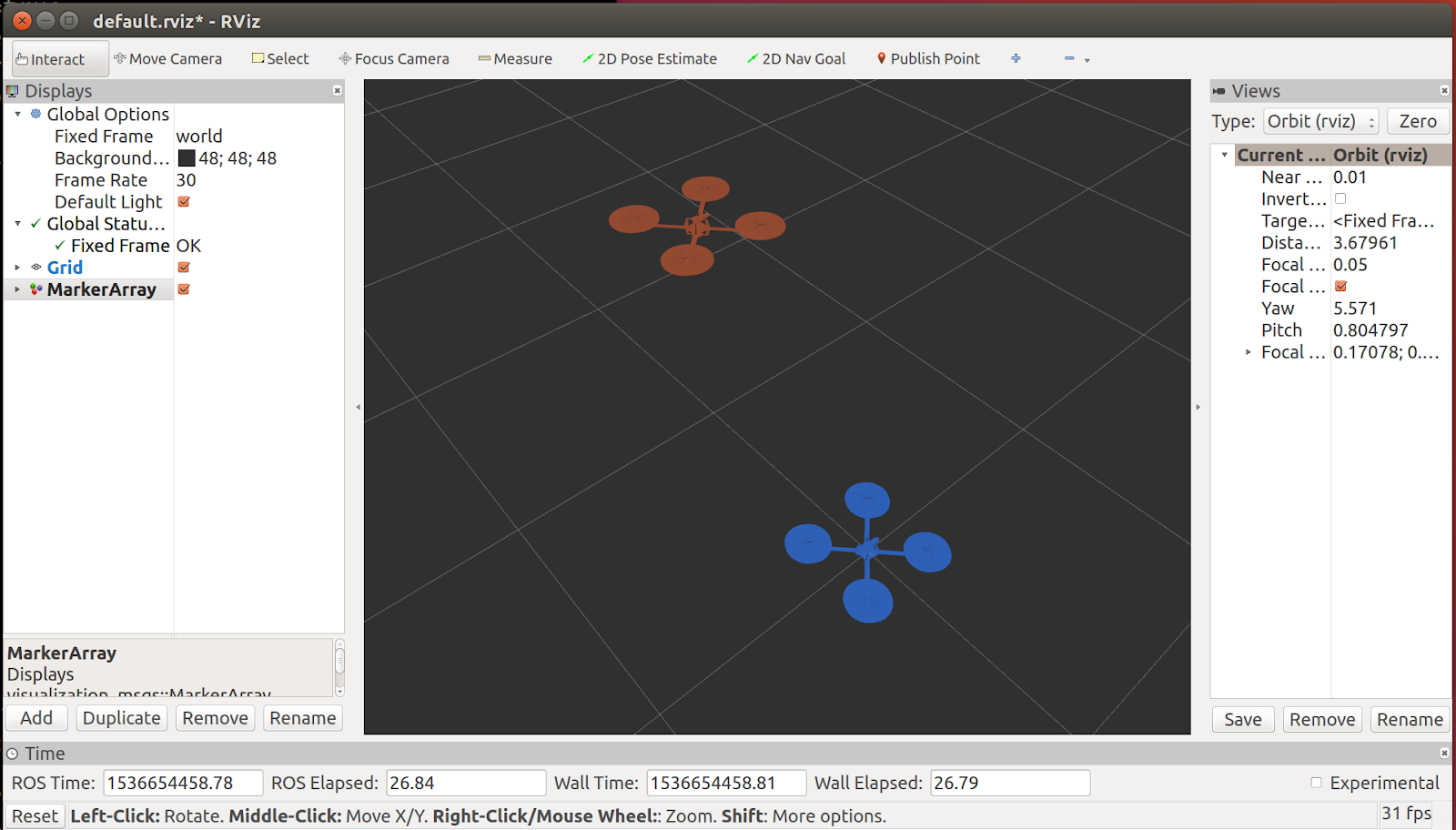
This window is rViz, the mighty ROS visualizer! Just like most processes in the ROS ecosystem, rViz is a ROS node. Like all other nodes, rViz can subscribe to ROS topics. However, its specialty is converting them into graphics on your screen to display the state of your robotic system.
As a first experience with rViz, let us:
- Add the visualization of
/tf. In the Displays panel, click Add, select the By display type Tab in the pop-up and finally select “TF” and confirm with Ok. You should see all the reference frames, with names and their axes represented in red (x), green (y) and blue (z). - Save the configuration file. So that we don’t have to repeat the step above every time we launch it! Hit CTRL + s or select File > Save Config.
Other published topics can be added to the visualizer in a similar way.
Problem formulation
We consider the scenario illustrated in the picture below, where two aerial vehicles, AV1 [blue] and AV2 [red] are following different trajectories: a circle and an arc of parabola, respectively. In the scene, we have highlighted the following elements:
- The world frame $(x_w, y_w, z_w)$
- The AV1 body frame, centered in $O_1$ with axes $(x_1,y_1,z_1)$
- The origin of AV2, denoted with $O_2$
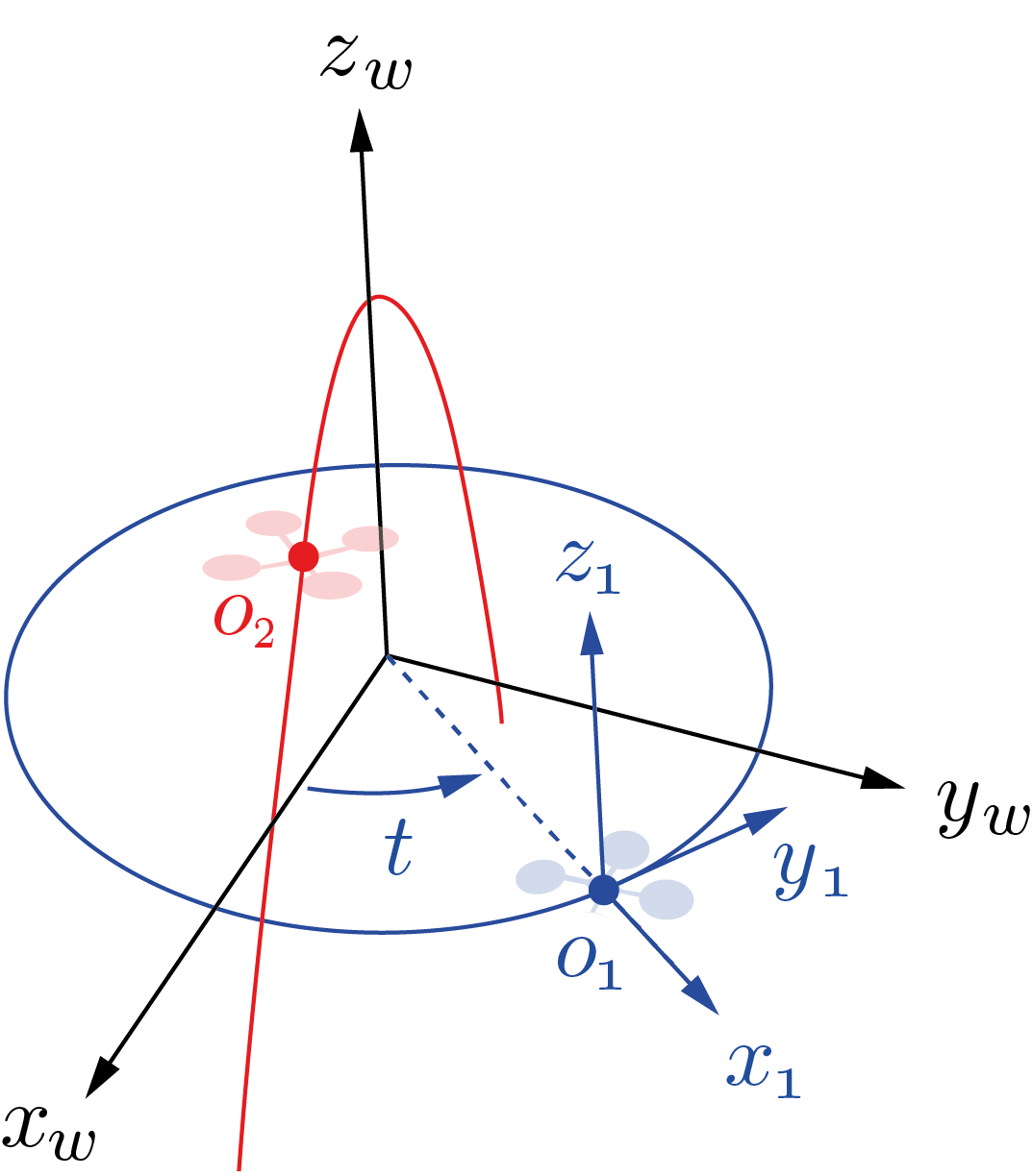
Positions
In the world frame, AV1 and AV2’s origins are given by:
- $o_1^w = [\text{cos}(t), \text{sin}(t), 0]^T$, and
- $o_2^w = [\text{sin}(t), 0, \text{cos}(2t)]^T$,
where $t$ denotes time.
Orientations
We will make the following simplifying assumptions:
- AV1’s reference frame is such that $y_1$ stays tangent to AV1’s trajectory for all $t$ and $z_1$ is parallel to $z_w$ for all $t$ (i.e., equivalently, roll = pitch = 0, yaw = $t$)
- AV2’s reference frame moves with pure translation and we can assume that its axes are parallel to the world axes for all times $t$
Notes
- Given the dynamics of a quadrotor, these motions are dynamically infeasible. However, for the purpose of this lab, we disregard this fact and focus on the study of rigid transformations
- To make the math of this problem more interesting, we chose the $y_1$ axis to point in the direction of motion of the drone. However, do not forget that the standard convention is that $x_1$ should point forward!
In the sequel, we reproduce the above scenario in ROS and study the trajectory of AV2 relative to AV1’s coordinate frame.
Basic ROS commands
📨 Deliverable 1 - Nodes, topics, launch files (10 pts)
With the ros2 launch command above we have spawned a number of ROS nodes at the same time. Using your knowledge of ROS, answer the following questions:
- List the nodes running in the two-drone static scenario.
- Hint: you can directly inspect the launch file, use the
ros2 node listcommand, or get some help fromrqt_graph. You will notice that rViz is initially not shown in it but you can uncheck the Debug option for a full picture.
- Hint: you can directly inspect the launch file, use the
- How could you run the two-drone static scenario without using the
ros2 launchcommand? List the commands that you would have to execute (in separate terminals) to achieve the same result.- Hint:
ros2 run [...], try things out before finalizing your answer!
- Hint:
- List the topics that each node publishes / subscribes to. What nodes are responsible for publishing the av1, av2, frames? Which topic causes rViz to plot the drone meshes?
- Hint: uncheck items on the left pane in rViz until the meshes disappear, then check what node is publishing the corresponding topic
- What changes if we omit
static:=True? Why?- Hint: check out and briefly explain the if and unless keywords in the launch file
Let’s make things move! Publishing the transforms using tf
After exploring the static scenario, it’s time to implement the motions described in the problem formulation section and visualize them in rViz. With the editor of your choice, open frames_publisher_node.cpp in the src folder of two_drones_pkg. In this file, we provide a basic structure of a ROS node.
Some Context
Please take your time to familiarize with this code before modifying it. Although not mandatory, the pattern found in it is a very common way to implement ROS nodes:
- The node’s source code is encapsulated into a class,
FramesPublisherNode(line 11), which inherits fromrclcpp::Node. - In the constructor of the class (lines 20 to 32), one performs operations that need to be executed only once upon startup (e.g. typically, initializing subscribers and publishers),
- Using a Timer (lines 14 and 27), the
onPublish()method is called periodically - at a 50Hz - and all the operations within it are performed ad libitum, - In the body of
main()(towards the end of the file):- the node is registered with
rclcpp::init(...) - an instance of the node class is created
- a blocking call to
rclcpp::spin()is issued, which starts ROS’s main loop.
- the node is registered with
📨 Deliverable 2 - Publishing transforms (30 pts)
In frames_publisher_node.cpp, follow the instructions in the comments and fill in the missing code. Your objective is to populate the provided world_T_av1 and world_T_av2 variables to match the motions described in the problem formulation. These objects are instances of the geometry_msgs::msg::TransformStamped class, which is a ROS message type representing a homogeneous transformation matrix (at a specific instance in time).
Keep in mind.
Ensure that the orientation of the AV1 frame is in accordance with the assumptions made in the problem formulation, as this is of crucial importance for the final result!
How to test
Once you are ready to compile your code, run:
colcon build
from the workspace folder ~/vnav_ws.
To try out your code, launch the two-drone scenario in non-static mode, i.e. run:
ros2 launch two_drones_pkg two_drones.launch.yaml
What to expect
You should finally see the drones moving! Check that the trajectories reflect those illustrated in the figure in the problem formulation.
Changing the rViz fixed reference frame.
As mentioned, we are interested in the motion of AV2 relative to AV1’s reference frame. In the Displays panel (left, by default), under the Global Options section, rViz offers the possibility to change the Fixed Frame to any frame published in tf. Try it out yourself and change “world” into “av1” by typing in the corresponding field. From this perspective, AV1 appears static, the world frame spins around its $z$ axis and AV2 seems to be following a closed-curve trajectory.
📨 Deliverable 3 - Looking up a transform (30 pts)
In plots_publisher_node.cpp, follow the instructions in the comments and fill in the missing code. Your objective is to populate the provided object, transform, with the relative transform between two given frames with names ref_frame and dest_frame.
Compile your code and try it out as previously explained.
What to expect
You should eventually see three trajectories, namely:
- AV1’s trajectory [blue, solid] in the world frame (circle on the x-y plane)
- AV2’s trajectory [red, solid] in the world frame (parabola on the z-x plane)
- The trajectory of AV2 in AV1’s frame [red, dashed]. You should now have a strong hunch that this curve is a ellipse on a “slanted” plane!
Note: if the results you are observing do not seem to make sense, try swapping ref_frame and dest_frame when interrogating \tf.
Let’s do some math
So far, we have used ROS and tf to get a visual understanding of the motion of AV2 relative to AV1’s body frame. In this section, you are asked to use your knowledge about homogeneous transformations and study the relative trajectory explicitly.
The visualization we have built should provide you with great guidance while working out the following questions. Since this exercise is designed for you to familiarize with the math of 3D transformations, we require that you explicitly write down all the homogeneous transformation matrices used in the process and precisely outline the logic and algebraic steps taken.
📨 Deliverable 4 - Mathematical derivations (25 pts)
- In the problem formulation, we mentioned that AV2’s trajectory is an arc of parabola in the $x$-$z$ plane of the world frame. Can you prove this statement?
- Hint: $cos(2t)$ can be written as…
- Compute $o_2^1(t)$, i.e., the position of AV2 relative to AV1’s body frame as a function of $t$.
- Hint: write down the homogeneous transformations and compose them accordingly…
- Show that $o_2^1(t)$ describes a planar curve and find the equation of its plane $\Pi$.
- Hint: find a linear relation between $z_2^1$ and $y_2^1$
- Rewrite the above trajectory explicitly using a 2D frame of reference $(x_p, y_p)$ on the plane found before. Try to ensure that the curve is centered at the origin of this 2D frame and that $x_p$, $y_p$ are axes of symmetry for the curve.
- Hints:
- i) center the new 2D frame in $p^1= (-1,-1/2,0)$, these coordinates are in AV1’s frame
- ii) start with a 3D reference frame centered in p with axes $(x_p, y_p, z_p)$, compute $o_2^p(t)$
- iii) make sure that the $z$ component vanishes after the change of coordinates
- Using the expression of $o_2^p(t)$, prove that the trajectory of AV2 relative to AV1 is an ellipse and compute the lengths of its semi-axes.
- Hint: what is the general form of the equation of an axis-aligned ellipse centered in the origin?
📨 Deliverable 5 - More properties of quaternions (5 pts)
In the lecture notes, we have defined two linear maps $\Omega_1: \mathbb{R}^4 \rightarrow \mathbb{R}^{4\times 4}$, and $\Omega_2: \mathbb{R}^4 \rightarrow \mathbb{R}^{4\times 4}$, such that for any $q \in \mathbb{R}^4$, we have:
\[\Omega_1(q) = \begin{bmatrix} q_4 & -q_3 & q_2 & q_1 \\ q_3 & q_4 & -q_1 & q_2 \\ -q_2 & q_1 & q_4 & q_3 \\ -q_1 & -q_2 & -q_3 & q_4 \end{bmatrix}, \> \Omega_2(q) = \begin{bmatrix} q_4 & q_3 & -q_2 & q_1 \\\ -q_3 & q_4 & q_1 & q_2 \\\ q_2 & -q_1 & q_4 & q_3 \\\ -q_1 & -q_2 & -q_3 & q_4 \end{bmatrix}.\]The product between any two unit quaternions can then be explicitly computed as: \[ q_a \otimes q_b = \Omega_1(q_a) q_b = \Omega_2(q_b)q_a. \] In fact, the two linear maps $\Omega_1$ and $\Omega_2$ have more interesting properties, and you are asked to prove the following equalities:
- For any unit quaternion $q$, both $\Omega_1(q)$ and $\Omega_2(q)$ are orthogonal matrices, i.e., \[ \Omega_1(q)^T\Omega_1(q) = \Omega_1(q)\Omega_1(q)^T = I_4, \] \[ \Omega_2(q)^T\Omega_2(q) = \Omega_2(q)\Omega_2(q)^T = I_4. \] Intuitively, what is the reason that both $\Omega_1(q)$ and $\Omega_2(q)$ must be orthogonal?
- Hint: what does $q_a \otimes q_b$ still being a unit quaternion imply?
For any unit quaternion $q$, both $\Omega_1(q)$ and $\Omega_2(q)$ convert $q$ to be the unit quaternion that corresponds to the 3D identity rotation, i.e., \[ \Omega_1(q)^Tq = \Omega_2(q)^Tq = [0,0,0,1]^T. \]
- For any two vectors $x,y \in \mathbb{R}^4$, show the two linear operators commute, i.e., \[ \Omega_1(x) \Omega_2(y) = \Omega_2(y) \Omega_1(x), \] \[ \Omega_1(x) \Omega_2(y)^T = \Omega_2(y)^T \Omega_1(x). \]
📨 [Optional] Deliverable 6 - Intrinsic vs Extrinsic rotations (20 pts)
Consider the following sequence of rotations:
- $R_0$: 90° around $x$
- $R_1$: 180° around $y$
- $R_2$ -30° around $x$
A) Extrinsic
The sequence of rotations is applied with respect to a fixed frame of reference (the world frame), as follows:
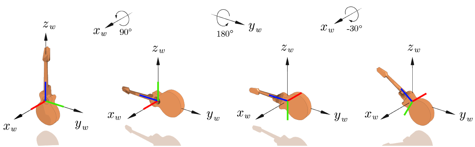
Note: the body axes are unlabeled, but represented in red ($x_b$), green ($y_b$), blue ($z_b$)
B) Intrinsic
The sequence of rotations is applied in reverse order with respect to a frame of reference attached to the object (the body frame), as follows:
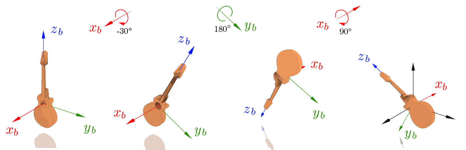
Note that the final orientation of the object is the same in both cases!
This property is quite general: it holds regardless of the specific axes and angles of the rotations and for any number of rotations in the sequence.
Could you prove this formally?
- Hint: prove that a rotation around a local axis (e.g., around x) is obtained by post-multiplying the given matrix (e.g., by $R_x$), while a rotation around the global axis is obtained by pre-multiplying. Then show the result easily follows from this fact. (It is acceptable that you prove the result for a single axis, e.g., $x$.)