Exercises
Submission
For this assignment, there is an individual component and a team component.
Individual
Please submit the individual deliveralbes (Deliverable 1 and Deliverable 2) on Gradescope, typeset in a PDF with LaTeX or other word processing software.
Team
Create a new repository in VNAV2024-submission called TEAM_<N>, replacing <N> with your team number. For example team 2 will create the repository TEAM_2.
Please push the source code of the entire controller_pkg package in the folder lab3 of the team repository.
Deadline
Deadline: the VNAV staff will clone your repository on September 25th, 2024 at 1pm.
Individual
Deliverable 1 - Transformations in Practice (10 pts)
This exercise will help you to understand how to perform transformation between different rotation representations using ROS. In addition, you will gain experience of reading through a documentation in order to find what you need.
A. Message vs. tf
In ROS, there are two commonly used datatypes for quaternions. One is geometry_msgs::msg::Quaternion and the other is tf2::Quaternion. Based on the documentation for tf2 and the tf2 tutorials, answer the following questions:
Assume we have an incoming
geometry_msgs::msg::Quaternion quat_msgthat holds the pose of our robot. We need to save it in an already definedtf2::Quaternion quat_tffor further calculations. Write one line of C++ code to accomplish this task.Assume we have just estimated our robot’s newest rotation and it’s saved in a variable called
quat_tfof typetf2::Quaternion. Write one line of C++ code to convert it to ageometry_msgs::msg::Quaterniontype. Usequat_msgas the name of the new variable.If you just want to know the scalar value of a
tf2::Quaternion, what member function will you use?
B. Conversion
The following questions will prepare you for converting between different rotation representations in C++ and ROS.
Assume you have a
tf2::Quaternion quat_t. How to extract the yaw component of the rotation with just one function call?Assume you have a
geometry_msgs::msg::Quaternion quat_msg. How to you convert it to an Eigen 3-by-3 matrix? Refer to this and this for possible functions. You probably need two function calls for this.
Deliverable 2 - Modelling and control of UAVs (20 pts)
A. Structure of quadrotors
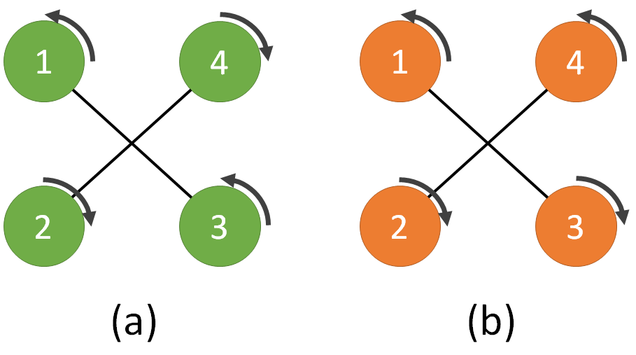
The figure above depicts two quadrotors (a) and (b). Quadrotor (a) is a fully functional UAV, while for Quadrotor (b) someone changed propellers 3 and 4 and reversed their respective rotation directions.
Show mathematically that quadrotor (b) is not able to track a trajectory defined in position $[x,y,z]$ and yaw orientation $\Psi$.
- Hint: write down the $F$ matrix (see lecture notes eq. (6.9)) for the two cases (a) and (b) and compare the rank of the two matrices
B. Control of quadrotors
Assume that empirical data suggest you can approximate the drag force (in the body frame) of a quadrotor body as:
\[ F^b = \begin{bmatrix} 0.1 & 0 & 0 \\ 0 & 0.1 & 0 \\ 0 & 0 & 0.2\end{bmatrix} (v^b)^2 \]
With $(v^b)^2= [-v^b_x \mid v^b_x \mid ,\, -v^b_y \mid v^b_y \mid ,\, -v^b_z \mid v^b_z \mid]^T $, and $v_x$, $v_y$, $v_z$ being the quadrotor velocities along the axes of the body frame.
With the controller discussed in class (see referenced paper 1), describe how you could use the information above to improve the tracking performance.
- Hint: the drag force introduced above is an additional term in the system’s dynamics, which the controller could compensate for explicitly…
Team
Trajectory tracking for UAVs
In this section, we are going to implement the geometric controller discussed in class on a simulated drone.
Getting the codebase
Consistently with the folder structure introduced in previous assignments, we will navigate to our existing clone of the VNAV Labs repository and pull the latest updates:
# change the folder name according to your setup
cd ~/vnav/starter-code
git pull
Next, put the team submission repo that you just created into you colcon workspace.
cd ~/vnav_ws/src/
git clone <your team repo url>
Note that if the repo doesn’t have any commits yet, you won’t be able to clone it; instead, make a new directory in ~/vnav_ws/src.
In ~/vnav/starter-code/lab3 we now have the tesse_ros_bridge and the controller_pkg folders, which are both ROS packages. Let us copy these folders to the team repo inside VNAV workspace and build the workspace as follows:
cp -r ~/vnav/starter-code/lab3/ ~/vnav_ws/src/<team repo name>
In your ~/vnav_ws/src/<team repo name>/lab3 folder, you should see two folders: controller_pkg and tesse-ros-bridge. Then, we need install some Python dependencies:
cd ~/vnav_ws/src/<team repo>/lab3/tesse-interface
pip install -r requirements.txt  # Dependencies
pip install .

sudo apt install ros-humble-tf-transformations
pip install numpy==1.26.4
pip install -U transforms3d
pip install rospy2
sudo apt install ros-humble-ackermann-msgs
sudo apt install ros-humble-rviz-imu-plugin
Last but not least, we need to pull mav_comm into our workspace:
cd ~/vnav_ws/src && git clone https://github.com/ethz-asl/mav_comm.git -b ros2
At this point, you can either keep your lab 2 code or remove all the folders related to the previous labs. Either way, you need to compile the new code.
colcon build
source install/setup.bash
After doing so, please proceed here to download the binary executable for the simulator we are going to use for lab 3 (if you already downloaded this for Lab 1, you do not need to re-download it). Unzip the file, put the folder in ~/vnav-builds, and run the following commands:
cd ~/vnav-builds/lab3/
chmod +x lab3.x86_64
This will make sure you can run the executable in the command line.
Launching the TESSE simulator with ROS bridge
In a terminal window, run this command to start the simulator:
cd ~/vnav-builds/lab3/
./lab3.x86_64
Once the simulator starts, you should see the unity simulator (fig. below).
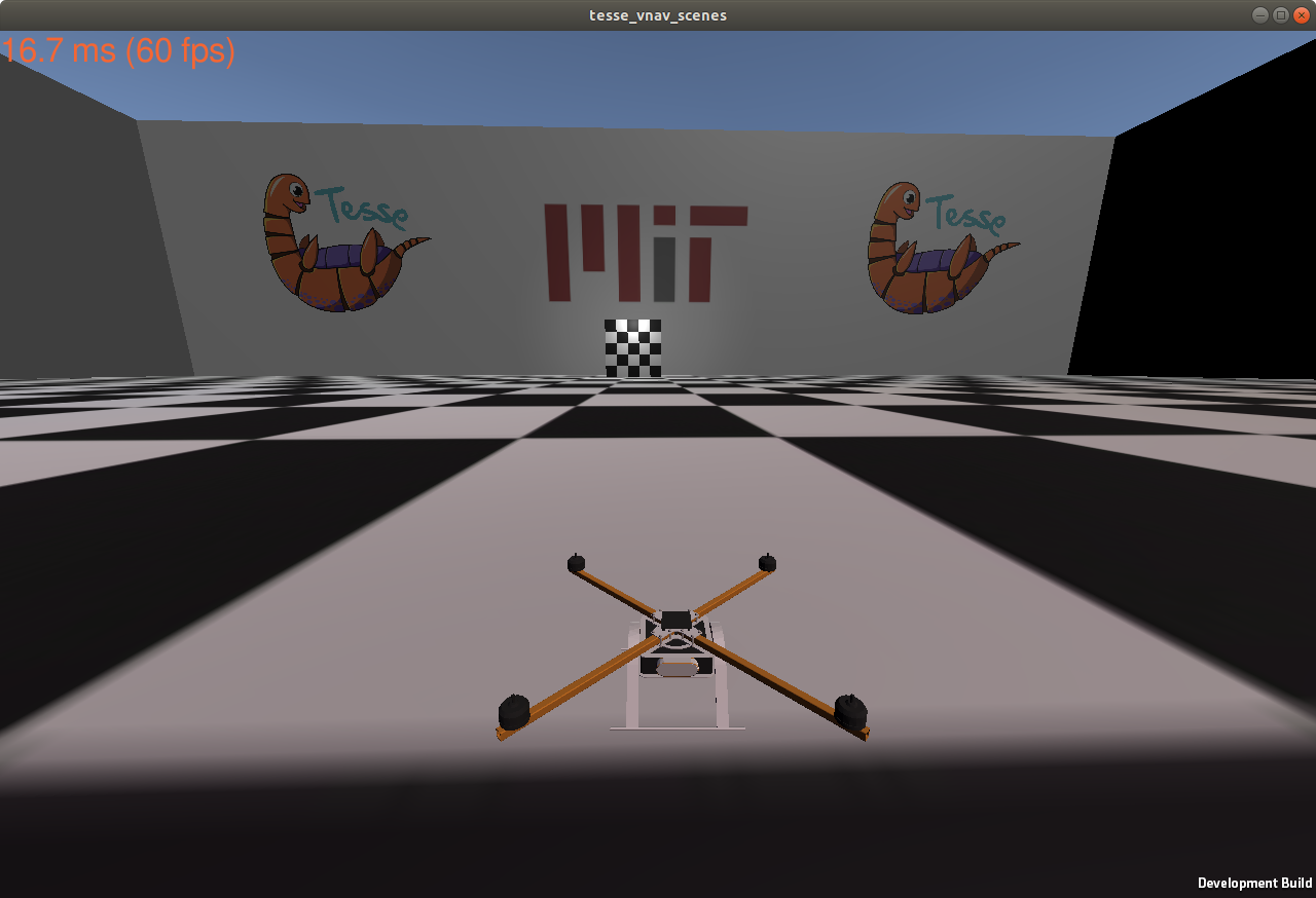
In the simulator, you can:
- press
Wto turn on all propellers; - press
Rto respawn the quadrotor at the initial location.
Note that you can resize the window to help with debugging later on.
Once the workspace has been compiled successfully, with your workspace sourced execute:
# make sure to source install/setup.bash!
ros2 launch tesse_ros_bridge tesse_quadrotor_bridge.launch.yaml
This launches two ROS nodes: tesse_ros_brige and quadrotor_control_interface. The former receives state messages from our simulator and publishes them in a few ROS topics, and the latter listens to our controller node and sends the propeller commands to our simulator. To visualize the state of our quadrotor, we will use rviz2. Run the following command to load our rviz preset:
cd ~/vnav_ws/src/controller_pkg
rviz2 -d rviz/lab3.rviz
You should see a screen similar to this:
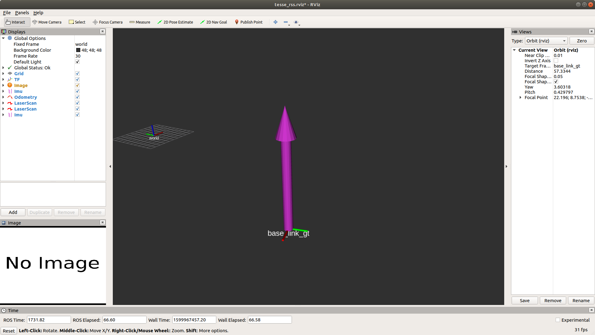
A few highlights:
- the purple upward arrow corresponds to the IMU message;
- the
base_link_gtaxes correspond to the body frame of the quadrotor; - the
worldaxes correspond to the world frame in ROS.
Implement the controller
From the previous section, you must have noticed that the drone is stationary. Unsurprisingly, this happens because the UAV is not receiving any control inputs. In this section, you will be precisely asked to take care of it!
Given four propeller speeds, the simulator propagates forward the UAV dynamics and outputs the current state of the robot. It is your job now to provide the propeller speeds based on the current state of the robot (from the simulator) and a desired one (from a trajectory generator). This problem is extensively described in the geometric controller paper 1, where the authors introduce an almost-globally convergent geometric controller for a quadrotor, also outlined in class. We will ask you to read the paper thoroughly and implement this controller in ROS.
For the purposes of this lab, the trajectory generator is given by the traj_publisher node, which outputs a time-varying desired state along a hard-coded circular trajectory. The navigation stack (almost) implemented in our codebase has the architecture shown below:
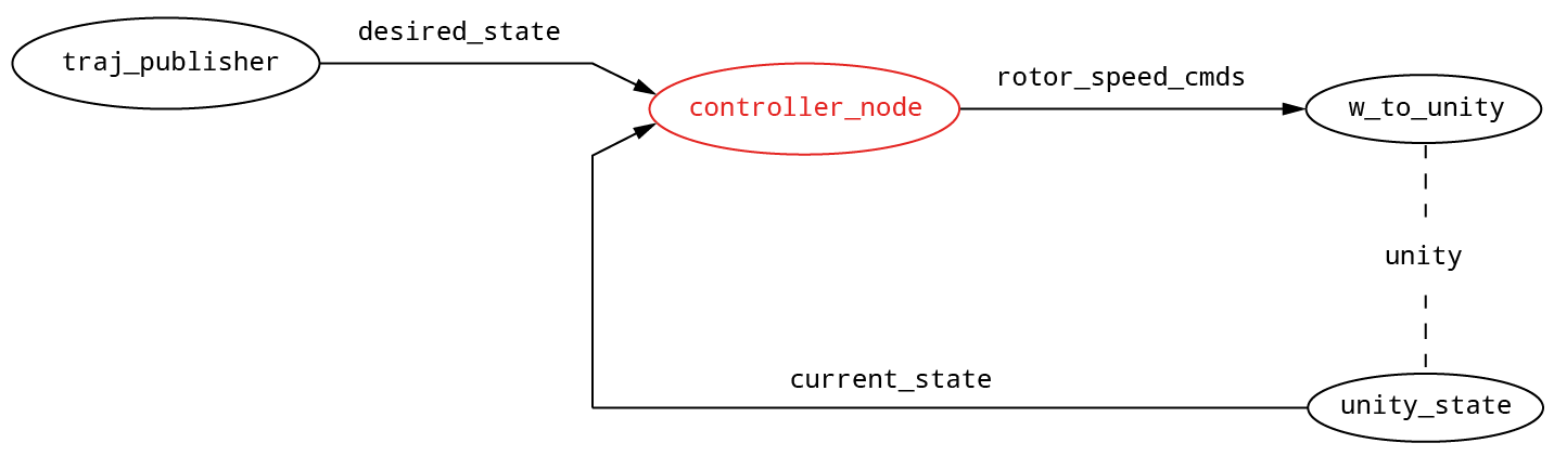
where the ROS nodes are highlighted as vertices in the graph and the ROS topic names are reported on the edges.
In particular:
/desired_stateis of type trajectory_msgs/msg/MultiDOFJointTrajectoryPoint and has the following fields:transforms- type geometry_msgs/msg/Transform:translation: a 3D vector with the desired position of the c.o.m. in the world framerotation: a quaternion rapresenting a rotation (in our case will be only a yaw component)
velocities- type geometry_msgs/msg/Twist:linear: a 3D vector with the desired velocity of c.o.m. in world frameangular: we will ignore this field as it is not used by the controller
accelerations- type geometry_msgs/msg/Twist:linear: a 3d vector with the desired acceleration of c.o.m. in world frameangular: we will ignore this field as it is not used by the controller
/current_stateis of type nav_msgs/msg/Odometry with the relevant fields:pose.pose- type geometry_msgs/msg/Pose:position: a 3d vector with the current position of the c.o.m. in the world frameorientation: a quaternion representing the current orientation of the UAV
twist.twist- type geometry_msgs/msg/Twist:linear: a 3d vector with the current velocity of c.o.m. in the world frameangular: a 3d vector with the current angular velocity in the world frame
/rotor_speed_cmdsis of type mav_msgs/msg/Actuators and it contains the relevant field:angular_velocities- typefloat64[], containing the desired speeds of the propellers.
Simulator conventions
In the picture below, we illustrate the conventions used in unity simulator for the propeller speeds and their positions in the body frame. Please look carefully as this will help you build the correct wrench-to-controls matrix (F2W) in the coding assignment
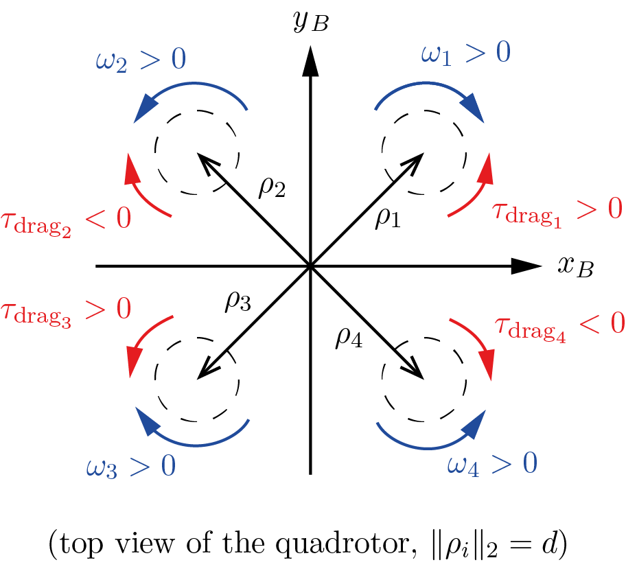
Note that
- as in most research papers, we assume that, for $\omega_i > 0$, all the propellers produce an upward force (lift). This is consistent with the first row of the matrix in eq. (6.9) on the lecture notes. While this might be confusing at first, note that on real quadrotors the motors are configured to rotate in different directions: two counter-clockwise (CCW), and two clockwise (CW). This configuration is necessary so that our quadrotor will be stable in its yaw direction. There are also two sets of propellers: one set for CCW motors, and another set for CW motors (both will produce upward force if mounted appropriately). See this video for an example.
- in the figure, we show the positive spinning directions for the propellers (blue) and the resulting direction of the yaw torques generated by aerodynamic drag. For example: propeller 1’s angular velocity $\omega_1$ is considered positive when propeller 1 spins clockwise (as seen from top), which in turn produces a counter-clockwise drag torque $\tau_{\text{drag}_1}$. The sign of the drag torque is determined by applying right-hand rule: positive for counter-clockwise, and negative for clockwise.
- the spinning directions are different from the paper. The expression $\tau_{\text{drag}}^i = (-1)^i c_d\,\omega_i | \omega_i |$ implies that the drag on propeller 1 produces a negative (clockwise) yaw torque instead, for $\omega_1$. However, the above convention is acceptable: propellers are mounted differently in the simulated quadrotor!
- the propeller speeds need to be provided in radians per second (rad/s), NOT in rpm. Initially, it will be tempting to go for the latter, as it will make the drone move more easily (control inputs get bigger), however, it will hurt you in the long run.
Before proceeding, keep in mind that there are a number of caveats that will make the math in your code slightly different from the one found in the paper. The main differences can be summarized as follows:
Reference frames. The paper and your code use different conventions for coordinate frames. Please refer to the figure and pay attention to the two main facts summarized below.
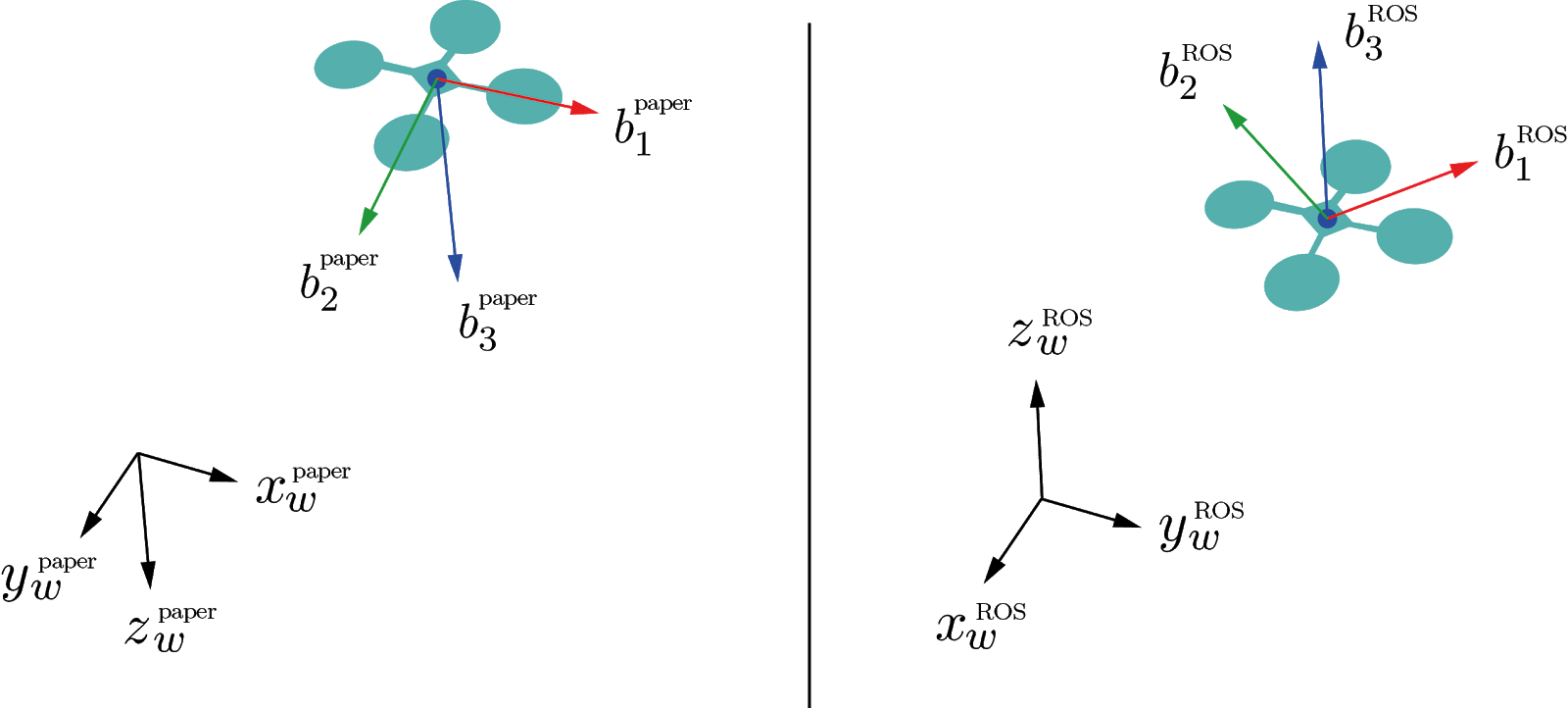
- In the paper, the $z$-axes - both in the world and body frames - are downwards, while ROS has them pointing upwards. This affects the signs of $b_{3_d}$ in equation (12), as well as gravity and aerodynamic forces in equations (12), (15), (16). (equation numbers refer to the paper 1).
- In the paper, the $x$-body axis is along a propeller arm, while we prefer having it at 45° between two propellers. This will require some thought on your end when converting the total desired force + torques (wrench) into the desired propeller speeds. In other words, you have to change equation (1) from the paper. For this step, refer to equation (6.9) in the lecture notes!
Aerodynamic coefficients. In the paper, equation (1), the quantity $c_{\tau f}$ relates directly the yaw torque with the lift produced by a propeller. In contrast, we prefer using the lift and drag coefficients $c_f$ and $c_d$, which have a clearer physical interpretation. Consider the relation $c_{\tau f}=c_d/c_f$ between these coefficients.
Deliverable 3 - Geometric controller for the UAV (50 pts)
After reading the reference 1 - thoroughly - get together with your teammates and open the source file controller_node.cpp. In this file, you will find detailed instructions to fill in the missing parts and make your quadrotor fly! To have full credits for this part of the lab, your team needs to complete the following:
- Implement all missing parts in
controller_node.cppand ensure everything compiles. - Tune parameters so that the quadrotor achieves stable circular trajectory.
- A video showing the quadrotor completing one round of the circular trajectory in
rviz(can either be a screen capture, or a video shot using your phone). Please upload the video onto either Google drive or Dropbox, generate a publicly viewable link, and put the link in a text file calledrviz_drone_flight.txtin your repo.
How to test
Once you are ready to compile your code, run:
colcon build
from the folder ~/vnav_ws.
To try out your code, launch the simulator. Additionally, run your controller by typing, in a separate terminal:
ros2 launch controller_pkg traj_tracking.launch
Depending on your focus - and degree of luck - it will take multiple attempts to have a stable and smooth controller and multiple iterations of parameter tuning. That’s normal!
As a suggestion, you could start by testing a stationary waypoint, before moving to the circular trajectory. This is possible by switching the STATIC_POSE flag to 1 in controller_pkg/src/traj_publisher.cpp. Also, you should use rviz to visually compare the desired and the current poses.
Tuning tips
First of all, look closely at the equations and see what are the gain parameters directly affecting. Which one affects the yaw? Which one affects the speed? Which one affects the position? Doing so will give you a rough idea on what to do for tuning.
To provide a more graphical/qualitative understanding, here are some typical situations that you might encounter:
komega is too high: 
kr is too low: 
kv is too low: 
NOTE: The specific gain parameters may differ across different computers.
What to expect
If your controller is working reasonably well we expect to see something like this: 
Note: it is totally fine if the drone does a rapid maneuver to start tracking the circle as soon as you run the controller node.
Good luck!